
Having STL File Issues?
Having STL File Issues?
(Part 2)
An STL file format is the most commonly used file type in 3D printing. All modern CAD (Computer Aided Design) software allows you to export their native file format as an STL file.
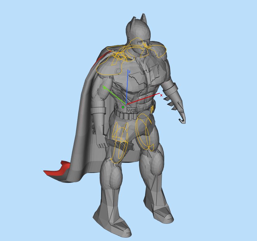
An STL file represents a 3D model by approximating it’s outer surfaces using multiple triangles. These triangles create a 3D network (mesh) of points, edges, and faces. This mesh defines the internal volume of the model.
Read below for the most common errors you may encounter while exporting a model as an STL file for 3D printing.
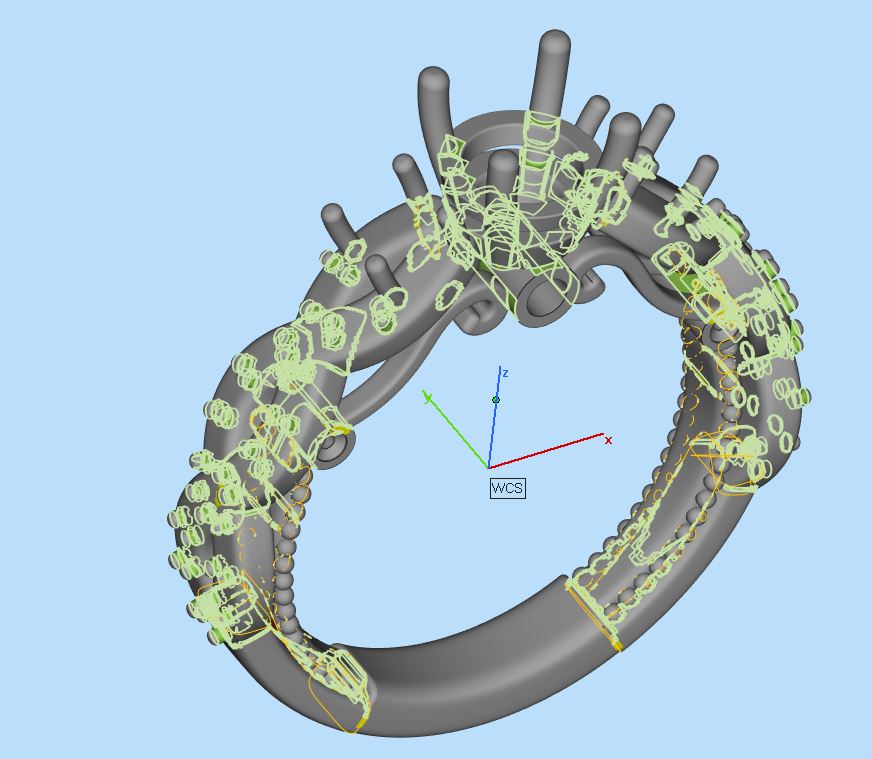
HOLE
When triangles are missing, they leave behind holes in a model. The slicing software may get confused in a similar way as with dealing with flipped (normal) triangles. The slicing software would not know where the model begins or ends and will result in a failed print job.
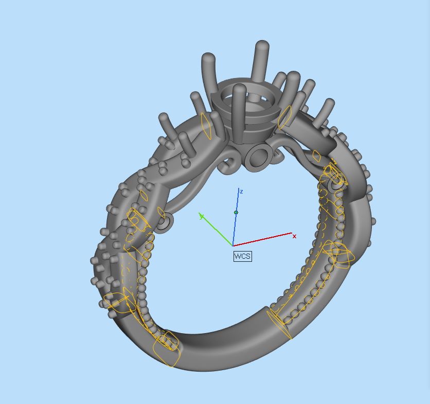
INTERSECTING TRIANGLES
Intersecting triangles that cut into one another are a common problem with 3D models. In order to correct this problem, the sharp edges need to be removed and trimmed from the intersected triangles to achieve a unified design.
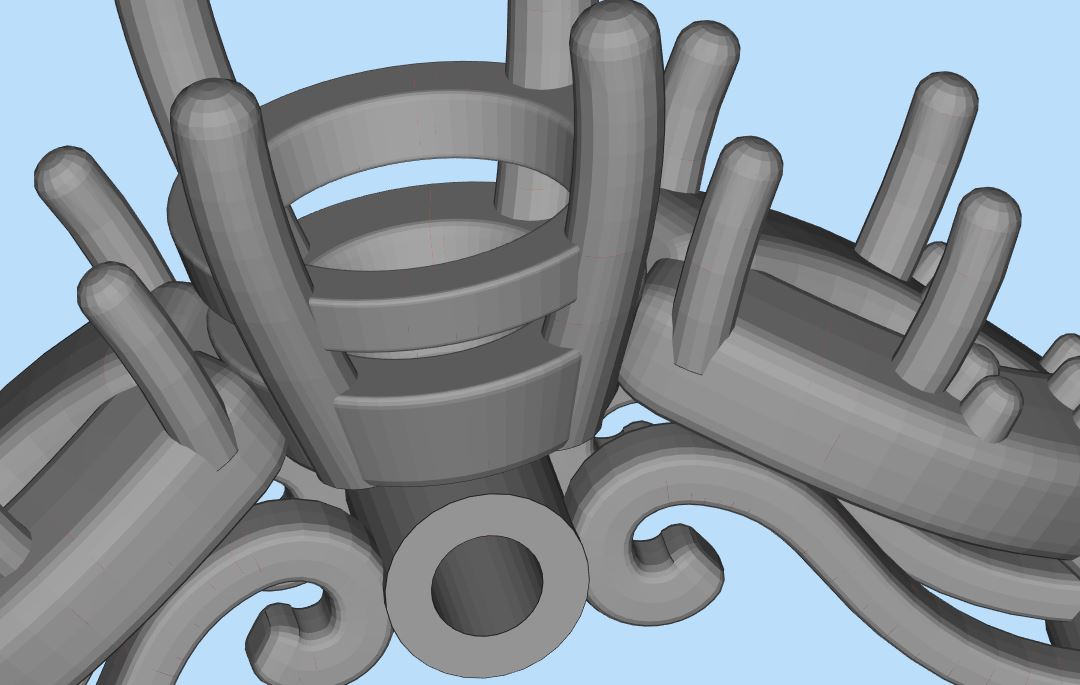
BAD SURFACE
STL employs a method of representing surfaces of a CAD model as a closed volume mesh comprised of triangles. The quantity and size of these triangles dictate how accurately the surface mesh represents the actual product. As the number of triangles increases and the relative triangle size decreases, the shape begins to more accurately represent the outline of the original CAD model. This is called "facet resolution." Typically, CAD products have a setting for STL chord height tolerance or mesh tolerance. This is the maximum perpendicular distance between a facet and the model surface, which is also the maximum error between the facet file and the CAD model. Maximum chord height should be 0.0005 inches (.0125 mm) but no less than 0.0001 inches (.0025 mm). A chord height tolerance greater than 0.005 inches (.125 mm) will produce visible facets, and will not decrease build times significantly.
Stay tuned for more STL file error information!
CONCLUSION:
Once you have managed to create or repair your STL file, you need to feed it into the slicing software. The slicing software (also called a slicer) converts the STL file into a machine code, the "g-code" which is basically the path per layer that the 3D printer must follow in order to construct the printed object. Stay tuned for our next article and find out more about the slicing software. We will provide a detailed selection of all software required to prepare and execute a 3D print. We hope that you have found this article useful!
Having STL File Issues? (Part 1)
An STL file format is the most commonly used file type in 3D printing. All modern CAD (Computer Aided Design) software allows you to export their native file format as an STL file.
An STL file represents a 3D model by approximating it’s outer surfaces using multiple triangles. These triangles create a 3D network (mesh) of points, edges, and faces. This mesh defines the internal volume of the model.
Read below for the most common errors you may encounter while exporting a model as an STL file for 3D printing.
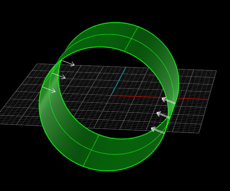
FLIPPED/INVERTED TRIANGLES/NORMALS
3D models have two sides: and outside and an inside. The outside is what you will see on the printed model, while the inside is what you will see if you cut a hole in the design. Since a CAD model is made out of triangles, it also has an inside and an outside. The outside of the triangle is called a “normal”. If the normal is flipped, it can cause issues with making water-tight STL files. If this happens, the printer’s slicing software could get confused and result in a failed print job.
BAD EDGES
Two or more triangles that are not connected to each other are defined as having “bad edges”. If a model contains bad edges, it will not be considered water-tight and will not print correctly. In this case, you will need to stitch together the bad edges in order to have a completed STL file that will print correctly.
BOOLEAN OPERATION
In a boolean joined model, a collection of triangles are interconnected to one another. Normally, a boolean joined model has to be only one shell because every triangle of the part is (indirectly) connected to every other triangle. This is different from Grouping. Grouping is a function that helps you move around a group of parts. The boolean operation creates a single watertight solid or surface that is ready to be exported into an stl and printed.
Stay tuned for more STL file error information!
CONCLUSION:
Once you have managed to create or repair your STL file, you need to feed it into the slicing software. The slicing software (also called a slicer) converts the STL file into a machine code, the "g-code" which is basically the path per layer that the 3D printer must follow in order to construct the printed object. Stay tuned for our next article and find out more about the slicing software. We will provide a detailed selection of all software required to prepare and execute a 3D print. We hope that you have found this article useful!
Log In